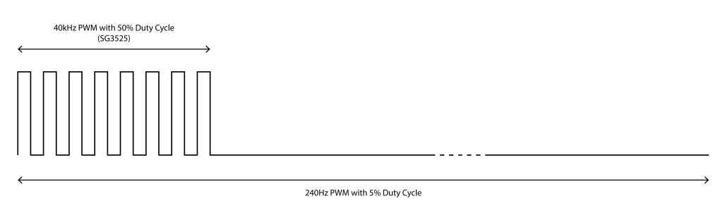
Distance measuring is based on firing pulse and measuring the flight time of sound waves. We clearly know that ultrasonic transducers are driven with 40kHz PWM signal. Continuous PWM signal will not satisfy the conditions of distance measuring. Hence, we should trigger the transmitters with another fully-controllable PWM signal to measure the distance.
We can’t use 555 timer in firing circuit because we don’t have fully control over it. Modulating 40kHz PWM (generated with SG3525) signal with 250Hz (generated with 555 timer) signal will be continuously trigger the transmitter. To be able measure distance, we should stop the firing pulse than wait for echo signal. Control over 555 time IC, we should add additional BJTs to control the firing signal. But this solution is not a preferable one. Instead of adding more components on circuit, we can generate the signal with 250Hz frequency using a microcontroller.
I will use NodeMCU ESP32 developer MCU. It does not matter which MCU you are using while you can generate desired PWM signal. Here is the desired firing signal and flowchart of the transmitter circuit are illustrated below.
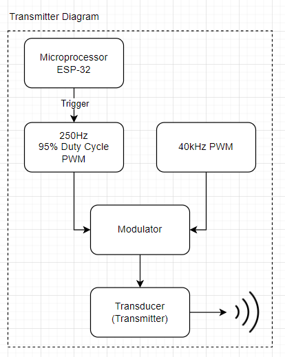
Microprocessor should calculate the PWM signal’s on&off delays for desired duty cycle. To generate the signal, we should specify frequency, duty cycle values than calculate the other important terms with some basic math. Code snippet shows the PWM generation process below.
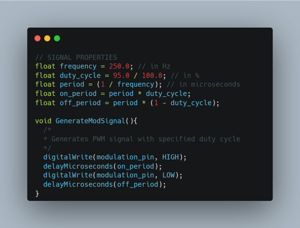
I did not mention about ‘modulation_pin’. You can set any output pin as modulation pin. With this code snippet, we are generating desired PWM signal on setted output pin. Now it is time to build the circuit to modulate the 40kHz signal with this generated PWM signal. I explained the SG3525 circuit in my old blog posts. If you want to learn how to generate PWM signal until 500kHz just read this blog post please. I will not explain same thing here again.
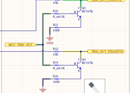
Here is the PWM square wave generator circuit. ‘Out A’ and ‘Out B’ pins are output pins of SG3525 IC. I setted the oscillacion frequency to 80kHz then I get 40kHz PWM square wave. To be able control the frequency, I just added a 20k ohm trimmer to RT pin. There is one more resistor different than VR1(trimmer) which annotated as R33. this resistor determine the base level of frequency when the trimmer is setted at 0 ohm.
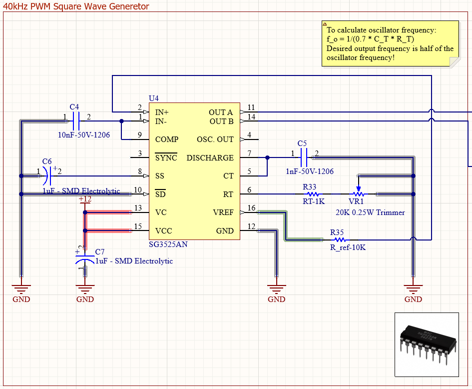
I used common-emitter topology for BJTs. This results inverse the signal, so I generated the signal with 95% duty cycle not with 5%. Because when BJT invert the 95% duty cycled signal, it will generate output with 5% duty cycle. If you want to learn more about topologies you can follow this link. If you want to learn common-emitter topology, you can follow this link.
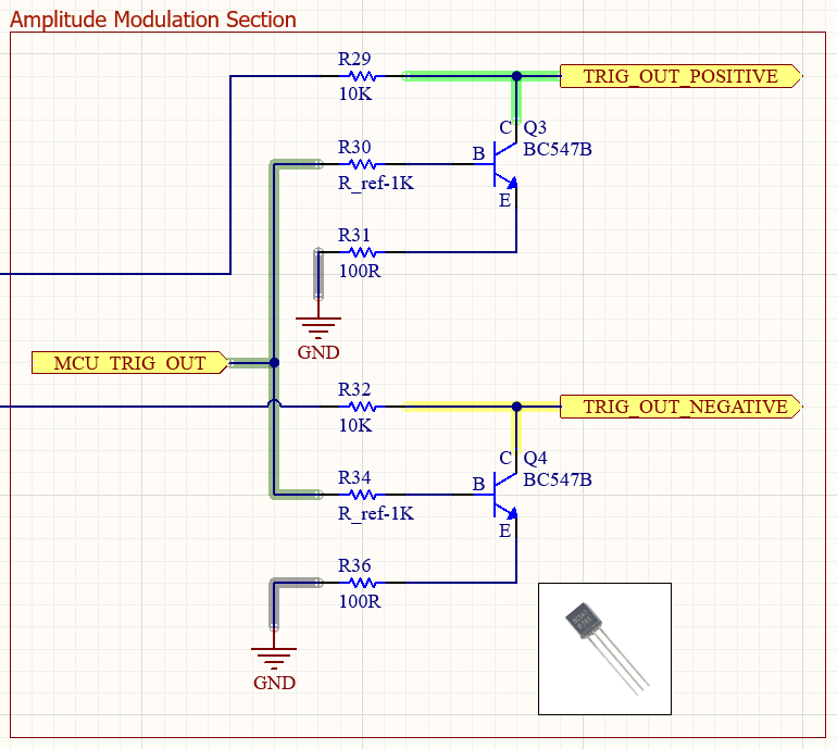
BC547 NPN BJT fit for this project. I connected both output A and B with two different BJTs and modulate the signal with the same PWM signal which I generate with MCU. Normally, you should calculate the values of collector, emitter and base resistors. I calculated the values for this project and this values are pretty good actually. But this type of resistor connection is not suggested. We are using the BJTs with different and more resistors in general. You can check the difference between the ideal connection and this one with using a SPICE software like QSpice or LTSpice.
With using this circuit we generate 250Hz signal than modulate the 40kHz PWM signal to trigger the transmitter. Then wait for echo waves and measure the time delay between beginning of triggering until receiving the echo signal. I told you about distance measurement in my past blog post. To determine the distance, we should divide the time with two. Because wave travel and reflect from an obstacle, it makes the path twice longer. We know the time and speed of sound so it is pretty easy to calculate the distance with these data.