Ultrasonic Transducer
Ultrasonics sensors are used for anti-collision safety, object detection, park sensors and more. For developing special kind of ultrasonic system to solve a problem, we should understand the working, driving and receiving principle of the ultrasonic transducers first.
Brief Introduction for HC-SR04 Ultrasonic Sensor and Ultrasonic Transducers
Ultrasonic transducers converts the electrical energy into ultrasonic vibrations or ultrasonic vibrations into electrical energy. In this article, I will examine ultrasonic transducers that work with ultrasonic sound waves.
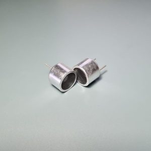
As shown in the Figure-1 there is one receiver and one transmitter exists. There is no driver or amplifier circuit connected to them. To be able drive this transducers, we should examine the principles of the receiver and transducers separately.
By reviewing a device that already exists, we can more easily understand how to use them and get a clean start. Let’s examine the HC-SR04 physically.
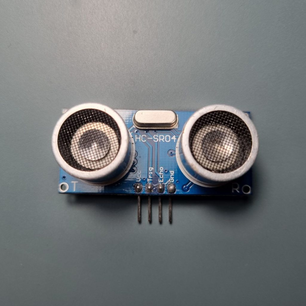
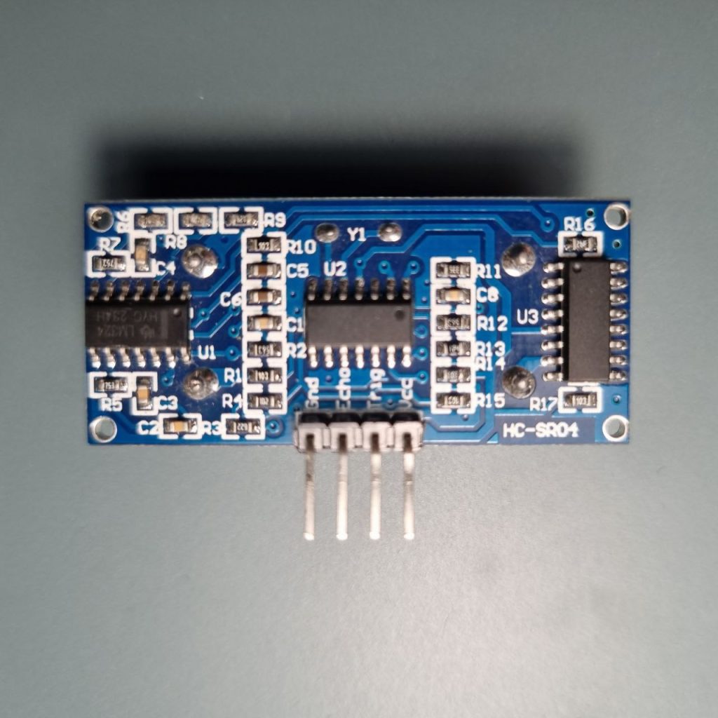
As shown in the Figure-2 and Figure-3, same transducers used for HC-SR04 module. When we examine the pin structures, we see VCC, GND, Trig and Echo pins. The supply voltage of the module is 5V. Let’s examine backside of the HC-SR04 module. Back view of the module shown in the Figure-3. There are two nameless integrated circuit and one LM324 IC. LM324 is a single supply quad operational amplifier integrated circuit. For technical information you can examine the related data-sheet.
For more information: the data sheet of LM324
Transmitter of the HC-SR04 module generates 40kHz ultrasonic sound wave and receiver of the module detects reflected sound waves. Sound wave propagates in air medium. After generating the sound wave, the signal propagates until collides with any object then reflects from the object. Receiver of the HC-SR04 module detects the reflected sound waves. When we want to determine how far is the collided object is, we should apply the following basic physics formula:
We know the speed of the sound in air medium. To determine time, we can easily calculate the duration between trigger time of transmitter and receiver. This duration will give us the propagated distance of generated and reflected sound wave signal. To calculate the distance between module and object, we should divide the distance with two. Because the sound wave first propagates towards the object and then hits the object and is reflected back. It makes the propagated path two times longer. This is the fundamental of distance measurement with ultrasonics sound waves.
The LM324 IC (integrated circuit) could be used as filter or instrumentation amplifier. To be able to understand logic of this module, we can examine the related papers. First, let’s examine how the transmitter works.
Fundamentals of Transmitter
When we examine the HC-SR04 ultrasonic sensor module, there is a 40 kHz crystal exists on the front side of it. To generate a sound wave, we should apply a signal to the input of the transducer. Crystal can generate a square-wave to drive the transmitter.
There is a black ring on one of the sensor legs. It would be logical to use this ringed lead as a signal leg. It would be more logical to select the other leg as GND, as it would also ground the chassis. This small ring may allow the signal to have less noise. These small rings shown clearly in the Figure-4.
Leave a Reply